
Installation Steps for Multi-Unit Screw Jack Systems
2025-12-01 10:29:44
Click:
“
When multiple screw jacks operate in synchronization, precise installation ensures balanced load distribution, motion accuracy, and long-term reliability. Below are the key steps for installing a multi-unit screw jack system
”
Screw jacks are critical components in industrial automation, heavy-load lifting, and precision positioning applications. When multiple screw jacks operate in synchronization, precise installation ensures balanced load distribution, motion accuracy, and long-term reliability. Below are the key steps for installing a multi-unit screw jack system:
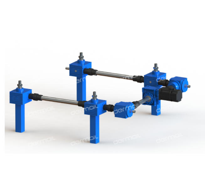
1. Pre-Installation Preparation
- Site Inspection & Layout Design
- Ensure the installation surface is flat, rigid, and free of debris.
- Select a layout pattern (e.g., linear, T-shaped, H-shaped, or U-shaped) based on load requirements and workspace constraints.
- Reserve space for tail tube installation (e.g., excavate pits or install steel support frames).
- Equipment Verification
- Inspect all components (screw jacks, motors, couplings, connecting rods, and controllers) for damage or missing parts.
- Verify that screw threads are smooth and free of burrs or defects.
- Tool & Safety Readiness
- Prepare tools: Leveling instruments, dial indicators, torque wrenches, and thermal installation equipment (for couplings).
- Ensure personnel wear safety gear (gloves, goggles, and helmets).
2. Mechanical Installation & Alignment
- Positioning & Leveling
- Place dermail screw jack units at predetermined locations. Use shim plates to adjust height differences between units (error ≤ ±0.1 mm/m).
- Ensure the installation surface has a flatness tolerance of ≤0.5 mm per meter. Use a leveling instrument for multi-point verification.
- Coupling Installation
- Clean coupling surfaces and bores to remove contaminants.
- Install couplings using thermal expansion (heat to 120–150°C) or cold-shrink methods. Avoid hammering to prevent shaft damage.
- Align shafts with a dial indicator to ensure coaxiality error ≤0.1 mm/m and end-face runout ≤0.05 mm.
- Connecting Rod & Linkage Setup
- Select connecting rods based on torque requirements (common diameters: Φ25–Φ50 mm).
- Ensure rods are corrosion-resistant (e.g., chrome-plated) and structurally stable.
- Verify that the linkage system allows smooth motion without binding or misalignment.
- Guide Rail Installation (If Required)
- Install guide rails parallel to the screw axis to prevent radial loads.
- Check for free movement within the travel range without jamming.
3. Electrical System Integration & Synchronization
- Motor & Controller Wiring
- Connect motors, encoders, and controllers according to the electrical diagram.
- Use cables with appropriate specifications and ensure proper insulation.
- Synchronization Configuration
- Mechanical Synchronization (Single-Motor Drive)
- Use a single motor with a transmission shaft or couplings to distribute power evenly.
- Ensure motor speed error ≤1% to maintain uniform motion.
- Electrical Synchronization (Multi-Motor Drive)
- Equip each motor with an encoder (e.g., absolute encoder) for closed-loop control.
- Use a PLC or motion controller with synchronization algorithms (e.g., PID control) to minimize positional error (≤±0.1 mm).
- Implement real-time communication protocols (e.g., EtherCAT) for nanosecond-level synchronization.
- Mechanical Synchronization (Single-Motor Drive)
- Safety & Limit Systems
- Install upper/lower limit switches (trigger distance: 50–100 mm from end positions).
- Add torque limiters or current monitoring to prevent overload.
- Design an emergency stop function to halt all units if one fails.
4. Lubrication & Trial Run
- Lubrication
- Fill gearboxes with industrial gear oil (e.g., ISO VG320).
- Apply lithium-based grease to screw threads to reduce friction and noise.
- No-Load Trial Run
- Operate the system empty for 2 hours to check for abnormal vibrations or noises.
- Verify that all units move in unison without significant phase differences.
- Load Increment Testing
- Gradually increase the load in 20% increments until reaching the rated capacity.
- Avoid sudden full-load startup to prevent mechanical shock.
- Error Correction
- If synchronization errors exceed tolerances, recalibrate PID parameters or check for mechanical misalignment.
- If synchronization errors exceed tolerances, recalibrate PID parameters or check for mechanical misalignment.
5. Final Inspection & Maintenance
- Acceptance Criteria
- Confirm synchronization accuracy, load distribution, and operational stability meet design specifications.
- Inspect all connections for tightness and lubrication levels.
- Long-Term Maintenance
- Select equipment with an IP54 or higher protection rating for dusty/humid environments.
- Replace seals every 500–800 operating hours and bearings every 1,000–1,500 hours.
- Schedule regular inspections to detect wear or misalignment early.
Key Takeaways
Proper installation of multi-unit screw jack systems requires meticulous attention to mechanical alignment, electrical synchronization, and safety protocols. By following these steps, engineers can achieve high-precision, reliable performance in applications such as automotive assembly lines, heavy machinery, and aerospace manufacturing.








Tel:+86-317-7369999
E-mail: demai@demai.org
Mobile:+86-18653450543 (Wechat)
Address:No. 6, Haihe Road, economic development zone, Wuqiao County, Cangzhou City, Hebei Province

点击右上角
分享给朋友吧
Copyright ©2023 All Rights Reserved Hebei Demai Transmission Machinery Co.,Ltd.
Copyright ©2025 All Rights Reserved Hebei Demai Transmission Machinery Co.,Ltd.
